


Introduction
For electronics engineers, startup teams, or small and medium-sized electronics manufacturers new to SMT, SMT machines often seem more complicated than they actually are: Feeders, Nozzles, Fiducials, Flying cameras, Auto programming… All these technical terms can easily intimidate beginners.
In reality, the core logic of an SMT machine isn't complicated. Simply put, it needs to complete a full process: Feeding → Picking → Identification → Positioning → Placement.
Understanding these 5 steps means understanding the most important functions of a pick and place machine. Below, using the NeoDen N10P pick and place machine as an example, let's see how a modern SMT machine accomplishes these tasks.
Feeding System: How Does the SMT Machine Accurately "Pick Up" Components?
The first challenge an SMT machine must address is how to reliably deliver different types of electronic components to the pick position.
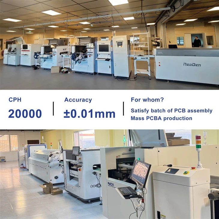
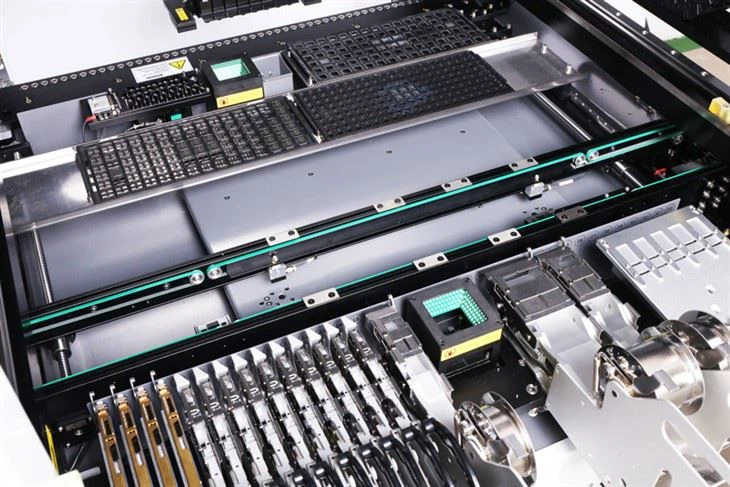
SMT components are typically fed in the form of tape, sticks, or trays, so the machine must be equipped with the corresponding feeders. The NeoDen N10P supports tape feeders, stick feeders, and tray feeders. Tape feeders are used for tape-and-reel components, stick feeders are suitable for stick-pack components, and tray feeders are primarily used for devices such as ICs.
The N10P also offers ample feeding capacity, supporting 80 tape feeders, 20 stick feeders, and 60 tray feeders, and allows for a mix of electric and pneumatic feeders.
1. Why does the SMT placement machine frequently fail to "pick up components"?
If the SMT placement machine cannot pick up components consistently, the problem may not necessarily lie with the machine itself. Common causes include offset in the pick-up position, improper pick-up height, a clogged or damaged nozzle, and insufficient air pressure.
The NeoDen N10P user manual also recommends starting the troubleshooting process by checking these parameters. For different components, parameters such as Pick Delay may need to be adjusted based on actual pick-up performance. For example, large-sized capacitors and 0402 components may require an appropriate increase in pick-up delay.
The NeoDen N10P's key advantage lies in its high-capacity feeding system, which can simultaneously manage a large number of different components, making it suitable for PCB production projects with a wide variety of components.
Vision Recognition: How Does the SMT Machine Know Where to Place Components?
If the feeder is responsible for "delivering the components," then the vision system is responsible for telling the machine "what this component is and how it should be placed."
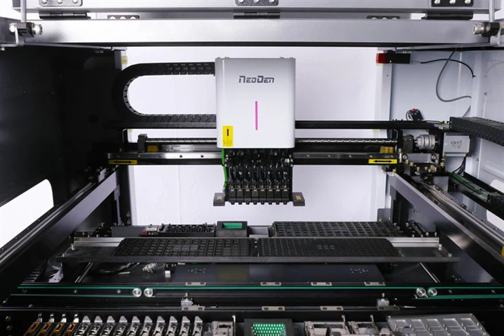
The NeoDen N10P is equipped with a Dual Mark Camera, a Front Flying Camera, and an IC Camera, which handle PCB reference positioning and the visual recognition of different component types, respectively.
Among these, the Fiducial Camera is used to identify reference points on the PCB. Since the PCB may be loaded with positional or angular deviations, the machine recalculates the PCB's origin and angle based on the fiducial points to correct the actual placement position.
1. Why can components still be placed accurately even if the PCB is slightly misaligned?
The Fiducial Align function described in the NeoDen N10P user manual calculates the actual position and angle based on the PCB's fiducial points. In other words, the SMT placement machine does not simply "place blindly" according to a fixed mechanical coordinate system, but rather positions components based on the PCB's actual condition.
2. Why do small components and ICs require different vision recognition methods?
Components with different packages vary in size, shape, and recognition requirements.
The N10P software offers recognition methods such as Fly Calib, IC Calib, and IC Rotate Calib. The Flying Camera can be used for common components such as resistors and capacitors; the IC Camera is suitable for ICs like SOPs, and the angle of precision ICs can be re-verified using IC Rotate Calib.
The advantage of the NeoDen N10P lies in its integration of the Mark Camera, Flying Camera, and IC Camera into a single device, creating a complete vision system for PCB positioning and component recognition.
High-Precision Placement: Why Can Components Be Placed Accurately on Pads?
The ultimate goal of a SMT placement machine is not merely to "pick up a component," but to place it accurately at the designated position on the PCB.
The NeoDen N10P has a positioning accuracy of ±0.01 mm, with feedback control for XY motion provided by magnetic linear encoders.
However, in actual production, placement accuracy does not depend solely on the equipment's nominal accuracy. Parameters such as PCB origin, fiducials, nozzle center, pick-up position, pick-up height, and placement speed all affect the final result.
1. What to Do About Placement Offset? Check These 5 Areas First
If components are placed crookedly or out of position, prioritize checking the following:
- Whether the fiducial is correctly recognized.
- Whether the PCB origin is correct.
- Whether the nozzle center is accurate.
- Whether the pick-up position has shifted.
- Whether the placement height and placement speed are appropriate.
The NeoDen N10P User Manual lists vision recognition errors, changes in the fiducial camera position, and inaccurate nozzle center as possible causes of accuracy anomalies, and provides adjustment methods such as camera calibration and nozzle fine calibration.
2. Why can't all components be placed at the same speed?
For standard components, production efficiency can be prioritized. However, for components smaller than 0402 and precision ICs, it is necessary to appropriately reduce the movement and placement speeds to improve placement stability and accuracy. The N10P software allows for separate adjustment of Move Speed and Place Speed.
The advantages of the NeoDen N10P include: 8 placement heads with closed-loop control, a maximum placement speed of 20,000 CPH, and motion feedback via magnetic linear encoders.
Automatic Nozzle Change: Why Does a SMT Placement Machine Need Multiple Nozzles?
1. Different components require different sizes and types of nozzles.
For example, small chips, capacitors, resistors, SOPs, larger ICs, and BGAs differ significantly in size and shape, so it is necessary to select the appropriate nozzle.
The NeoDen N10P supports a wide range of nozzle specifications, such as CN020, CN030, CN040, CN065, CN100, CN220, CN400, as well as nozzles suitable for ICs and BGAs of various sizes.
2. What happens if the nozzle doesn't match?
If the nozzle size is incorrect, it may result in insufficient suction, air leaks, pickup failures, or even component ejection. The manual also lists nozzle clogging, damage, and mismatched nozzle sizes as common causes of "Pick-up Failure" and "Throwing Components."
What is the practical value of automatic nozzle change?
The N10P SMT machine is equipped with 39 nozzle positions and supports automatic nozzle change.
This means that when a PCB contains multiple components with different package types, the machine can automatically select the appropriate nozzle based on the program, eliminating the need for operators to frequently stop the machine for manual changes.
The advantage of the NeoDen N10P lies in the combination of its 39-position nozzle bank and automatic nozzle change function, which enhances flexibility during the placement of high-variety PCBs.
Software and Automatic Programming: How Can Beginners Quickly Create Placement Programs?
For beginners, what really needs to be mastered is not every software button, but rather an understanding of the relationships between the PCB, components, feeders, nozzles, and placement sequences.
The N10P supports functions such as coordinate file import, manual programming, auto-programming, component libraries, footprint libraries, feeder assignment, and placement sequences.
1. How do you create a placement program when you have a PCB coordinate file?
The basic process can be summarized as follows:
Coordinate File → Import → Component Matching → Feeder Setup → Auto Program → Check → Production
After importing the coordinate file generated by PCB design software into the N10P, the system can match component information based on the Footprint Library. Next, set up the feeders and nozzles, then use Auto Program to assist in generating the placement sequence.
2. Is Auto Program completely automated?
No, it is not.
The purpose of Auto Program is to optimize nozzle usage, feeder allocation, and placement sequence based on the component information that has been entered. After the program is generated, the operator still needs to check the nozzle distribution, feeder distribution, and placement sequence.
The advantage of the NeoDen N10P lies in its Auto Program feature, which significantly reduces repetitive program configuration work-particularly helpful for PCBs with a wide variety of components.

The 5 Most Common SMT Placement Issues Faced by Beginners
Once you understand these 5 core functions, many common issues actually have clear troubleshooting paths.
- Feeder not feeding: Check feeder installation, tape reel, feeding parameters, and air circuit status.
- Components not being picked up: Prioritize checking the pick-up position, pick-up height, nozzle, and air pressure.
- Frequent component drop-offs: Check vision recognition, component footprint, nozzle size, and nozzle cleanliness.
- Component placement misalignment: Check the fiducial, nozzle center, and camera calibration.
- Issues during the first production run: It is not recommended to proceed directly to mass production. The N10P user manual recommends following this sequence: Dry Run → First Production Test → Component Inspection → Continuous Production. After verifying the component specifications, orientation, polarity, and position on the first piece, proceed to continuous production.
For which production scenarios are desktop SMT pick and place machines suitable?
For PCB prototyping, R&D validation, and small- to medium-volume SMT production, the flexibility of the equipment is often just as important as its speed.
The N10P supports a large number of feeders, automatic nozzle change, vision recognition, and automatic programming, making it particularly well-suited for PCB projects involving multiple varieties, different package types, and a certain level of placement efficiency.
For long PCBs, the N10P can support PCBs up to 1,500 mm in length when configured with an extension conveyor.
Therefore, when selecting an SMT pick and place machine, rather than focusing solely on CPH, it is better to consider placement accuracy, component range, feeder capacity, vision systems, nozzle systems, PCB dimensions, and software capabilities as well.

Conclusion
An SMT pick and place machine is not simply an "automatic component placement machine."
It is, in fact, the result of multiple systems working in concert:
The feeder supplies components, the nozzle picks them up, the vision system identifies and positions them, the motion system moves them with precision, and the software coordinates the entire placement process.
If you are evaluating an SMT pick and place machine or planning to establish your own SMT assembly capabilities for PCB prototyping, R&D validation, and small-to-medium-volume production.