


Introduction
In modern SMT production lines, the temperature control accuracy and stability of reflow soldering equipment are key factors determining the final soldering quality. Many electronics manufacturers and engineers frequently encounter typical soldering defects such as component tombstoning, BGA cold solder joints, or solder balls.
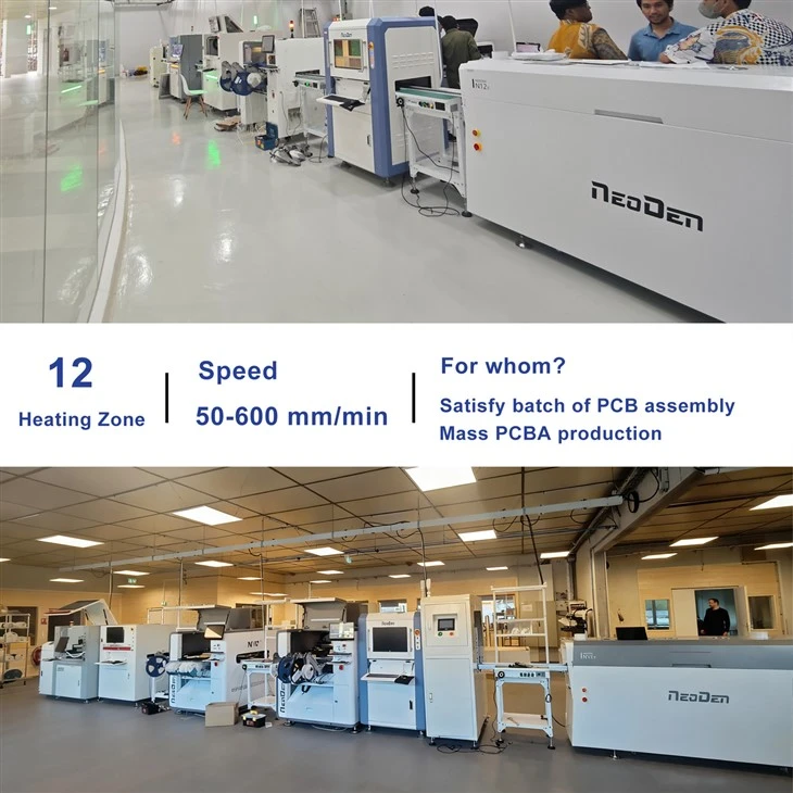
NeoDen IN12C reflow oven features 12 independent temperature zones, aluminum alloy heating plates, and a dedicated cooling zone design, making it suitable for soldering 0201 components as well as complex packages such as BGA, QFP, and QFN. To ensure the equipment maintains optimal process performance over the long term, this article compiles a guide for the daily maintenance and temperature calibration of the IN12C reflow oven based on the official user manual, with a focus on how to resolve solder ball issues by optimizing the temperature profile.

The Impact of Reflow Oven Maintenance on SMT Yield
In terms of mechanical design, the NeoDen IN12C incorporates several optimizations to reduce routine mechanical wear:
- One-piece molded stainless steel Type B mesh chain: Traditional carbon steel chains are prone to rust when left idle for long periods and require frequent application of high-temperature lubricant during daily operation. The IN12C's mesh chain features a one-piece molded design with no riveted joints, preventing chain loosening caused by long-term high-temperature fatigue.
- Lightweight track structure: The total weight of the track assembly is kept below 5 kg, reducing the load on the drive motor and helping to extend its service life. At the same time, the lightweight track effectively improves temperature uniformity in the areas adjacent to the track.
Although the mechanical components reduce the frequency of routine lubrication, periodic cleaning of the air supply system and calibration of the temperature control sensors remain essential for maintaining a temperature control accuracy of ±0.5°C, as flux volatilizes at high temperatures and then condenses and accumulates.
NeoDen IN12C Basic Periodic Maintenance Procedure
To ensure the long-term stable operation of the equipment control system, the factory should establish the following standardized maintenance procedures:

1. Daily Startup and Three-Color Indicator Status Check: During the startup phase.
Check whether the circuit breaker and residual current device (RCD) are closed normally. After startup, determine the equipment status via the three-color status indicator on the top:
- A flashing yellow light indicates that the temperature zone is Heat-up.
- A steady green light indicates that all temperature zones have reached the set temperature.
- A flashing red light indicates a system malfunction, shut down the machine to troubleshoot.
2. Drive Mechanism and Mechanical Adjustment of Chain Width: Weekly maintenance.
Test the track width adjustment mechanism. If the electrical width adjustment button becomes unresponsive, use the manual width adjustment handles at both ends of the equipment to make manual adjustments, preventing track deformation caused by abnormal resistance at high temperatures.

3. Replacement of the built-in solder fume filtration system filter cartridge: Every 8 months / adjust based on production volume.
To maintain the airflow circulation efficiency of the hydrodynamic design and prevent air duct blockages, the filter cartridge must be replaced regularly:
- Remove the left wind shield on the left side of the equipment.
- Open the filter cover located in the concave area.
- Pull out the filter assembly and replace the carbon fiber cotton.
Reflow Solder Balls Defect Troubleshooting and Curve Optimization
1. Core Mechanism of Solder Ball Formation
Solder balls are a common defect in the reflow soldering process, typically forming between the preheating zone and the active zone.
If the temperature rise slope in the preheating section is too steep (generally controlled within 2°C/s), the solvents and flux inside the solder paste will evaporate violently or even "splatter." These tiny metal particles are ejected from the main pad due to the spattering. When they enter the reflow section and melt, they cannot reintegrate into the main solder joint, instead, they solidify into separate solder balls around the periphery of the pad upon cooling.
2. Process Adjustment Plan: Adjusting Conveyor Speed and Airflow in Temperature Zones
To address solder balls caused by excessive drying speed, process validation can be conducted by combining airflow adjustments with conveyor speed optimization.
Using the IN12C's 4-channel board surface temperature monitoring system, process parameters can be adjusted through the following steps:
- Thermocouple Placement: Secure the test thermocouples to typical locations on the PCB (such as the leads of large components, the center of IC pads, and the PCB edges) using high-temperature-resistant tape to capture accurate board surface temperatures.
- Real-Time Curve Analysis: Load the test board into the oven and observe the real-time measurement curves on the system screen.
- Fine-tune process parameters: The IN12C conveyor belt speed supports adjustment from 50 to 600 mm/min. When processing standard lead-free solder paste, it is recommended to maintain the belt speed at approximately 250–300 mm/min. At the same time, take advantage of the adjustable airspeed feature in each temperature zone to appropriately reduce the fan speed in the preheat zone. This slows down convective heat transfer, allowing sufficient time for the flux to evaporate steadily and reducing solder paste splatter caused by rapid boiling.
Recommended 4-Stage Temperature Zone Settings for Typical Reflow Soldering
When adjusting temperatures, note that the preset temperature of the heating unit is typically 20–40°C higher than the actual temperature reached on the PCB surface due to heat transfer losses.
Using a common lead-free solder paste (such as SAC305, with a melting point of 217°C) as an example, it is recommended to calibrate the temperature zone parameters according to the following four stages:
Note: The following parameters are typical process reference values for SAC305, the solder paste supplier's recommended curve should be followed.
| 4-Stage Soldering Process | Purpose and Temperature Zone Logic | Recommended Actual Board Surface Temperature Range | Equipment Hardware Configuration |
| 1. Preheating Zone | Slow temperature rise to volatilize solder paste solvents and activate the flux. | Room temperature ---> 140/150°C, heating rate <2°C/s. | Aluminum alloy heating plate to reduce transverse temperature differences. |
| 2. Constant Temperature/Active Zone | Minimize temperature differences among components on the board surface and remove oxides from the soldering surfaces. | 150°C-->190°C, maintained for 60–120 seconds. | Stainless steel inner chamber combined with thermal insulation material to retain internal heat. |
| 3. Reflow Zone | The solder paste is completely melted, forming an IMC (Intermetallic Compound) joint. | Peak temperature 230–245°C; time spent above the melting point 40–70 seconds. | Independent upper and lower temperature control modules provide efficient thermal compensation. |
| 4. Cooling Zone | Controls the cooling rate to achieve grain refinement in the solder joints. | Cooling rate controlled at -2 to -4°C/s. | Four independent circulating fans in the upper section reduce interference from the surrounding environment. |
Note: The IN12C can store up to 40 working files internally. After calibrating a qualified curve for PCBs with different numbers of layers and densities, it is recommended to save it as a separate file. This allows for one-click retrieval when switching to production of different products, ensuring consistency in process parameters.
Equipment Energy Consumption Management and Power Consumption Specifications
In long-term SMT production, the power consumption of reflow soldering equipment is a significant component of a factory's operating costs. According to the NeoDen IN12C technical specifications, its energy consumption metrics are as follows:
- Starting Power: ~4.8 kW
- Typical Working Power: ~2.2 kW
- Power Supply Configuration: Single-phase, single-wire AC 220V (can be directly connected to standard residential or industrial power grids).
Regular maintenance of the filtration system, keeping the fan air ducts clear, and calibrating the thermocouple sensors ensure that the machine delivers stable heat output at its standard operating power. If flux is not cleaned from the equipment over an extended period, clogged filter elements and obstructed airflow may impair the efficiency of the furnace's heat circulation, thereby affecting temperature uniformity. Therefore, it is recommended to perform maintenance promptly according to the official maintenance schedule. Routine maintenance not only extends the service life of the heating plates but also keeps the equipment operating within an optimal, low-power consumption range.
Conclusion
Consistent soldering quality is built on the foundation of appropriate temperature profiles and scientific daily maintenance. Through standardized daily inspections, regular cleaning of the airflow system, and precise calibration using the 4-channel board-level temperature measurement system, solder defects such as solder balls can be effectively controlled, ensuring that the reflow soldering equipment maintains a precise temperature control level of ±0.5°C throughout its entire lifecycle.