

Introduction
In modern SMT production, SMD machines are not only the core equipment of SMT lines but also the key factor determining product quality and production efficiency. As a high-speed, high-precision placement platform, the NeoDen N10P has earned the favor of global electronics manufacturers with its outstanding performance. However, even the most advanced equipment requires systematic, regular maintenance to sustain peak performance.
This document combines insights from the "NeoDen N10P User Manual" with professional maintenance expertise to provide SMT engineers, equipment operators, and production line managers with an actionable, implementable daily and monthly maintenance checklist. It helps maximize your return on investment (ROI), minimize downtime, and ensure consistent placement quality.
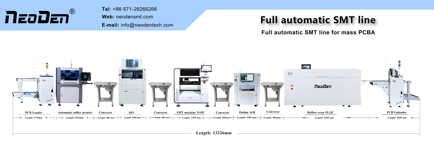
I. Why is Regular Maintenance Critical for SMT Production?
The NeoDen N10P is a complex system integrating precision mechanics, optical recognition, pneumatic control, and intelligent software. Its moving components (e.g., X/Y-axis lead screws, linear guides, Z-axis placement heads), vision systems (mark cameras, flying-probe cameras, IC cameras), and pneumatic components (solenoid valves, SMT Nozzles, air tubes) are highly sensitive to the working environment.
Dust, temperature/humidity fluctuations, and unstable air pressure in the environment can accumulate minute deviations over prolonged operation, ultimately manifesting as:
- Component placement misalignment
- Nozzle pickup failures or frequent component ejection
- Camera recognition errors
- Mechanical movement stuttering or abnormal noises
Regular maintenance-through proactive intervention, cleaning, calibration, and lubrication-ensures the equipment consistently operates within its factory-set high-precision parameters.
More importantly, standardized maintenance records provide engineers with critical diagnostic references during equipment repairs or after-sales support, accelerating problem resolution.
II. Daily Inspection Checklist: 5 Minutes to Ensure Smooth Production
The focus of daily maintenance is "prevention" and "quick verification." Spending just 5 minutes before startup can prevent 80% of common failures.
1. Pre-Startup Environmental Verification
- Temperature & Humidity Control: Maintain workshop temperature between 20°C–26°C and humidity at 45%–70%. Excessive humidity risks PCB moisture absorption and solder paste degradation; insufficient humidity increases electrostatic discharge risks. Extreme temperature fluctuations affect mechanical thermal expansion/contraction, compromising placement accuracy.
- Cleanliness Inspection: Visually confirm no debris, solder paste splatter, or waste accumulation along the placement head's travel path (X/Y-axis range), rails, nozzle magazine, or camera lens periphery. Any foreign objects may interfere with sensors or scratch equipment.
- Safety Check: Verify emergency stop buttons are not engaged, front/rear safety doors are closed, and equipment is properly grounded.
2. Critical Hardware Quick Checks
Air Pressure Verification: Confirm inlet pressure ≥ 0.6 MPa.
Note: Feeder pressure must be set to 0.6 MPa, pick-and-place head pressure to 0.55 MPa. When adjusting, lift knob before rotating to gradually change pressure, avoiding sudden impacts.
Nozzle Condition Check
- Visually inspect nozzle end face for contamination, blockage, cracks, or deformation.
- In the software's "Manual Test > Applicator" interface, click "Suction Test" to verify negative pressure ≤ -80 kPa (displayed as air pressure value). If negative pressure is insufficient, immediately clean or replace the nozzle.
- Feeder Installation Status: Ensure all feeders are fully seated in the feed stack with no lifting (front/rear feeder protection sensors should display green). Lifting feeders will trigger safety protection, causing machine shutdown.
3. Power-On Self-Test and Warm-Up
After powering on, observe whether the equipment completes the self-test normally and whether the placement head and XY axes successfully return to origin.
Activate the **"Machine Warm-up" function** and run for 10 minutes. Warm-up allows servo motors, guide rails, and lead screws to reach thermal equilibrium, significantly improving placement consistency. This is particularly crucial during early shifts or after extended downtime.
III. Monthly Deep Maintenance: The Core of Extending Equipment Lifespan
Recommended to be scheduled on the last working day of each month or during planned downtime.
1. Motion System Maintenance: Lubrication of X/Y-Axis Lead Screws and Linear Guides
This is the most critical maintenance task affecting placement accuracy. Lack of lubrication or dust accumulation on lead screws and linear guides can increase motion resistance, cause positioning errors, and even lead to wear.
X-Axis Maintenance Steps
- In the software under "Applications > Pick-up Head Movement," move the pick-up head to the far right (near the right Mark camera).
- Thoroughly wipe the X-axis linear guide and lead screw surfaces with a microfiber cloth to remove old oil, metal debris, and dust.
- Use an oil injector to apply specialized grease into the lubrication ports of the X-axis linear guide and ball screw nut.
- Control the applicator head via software to move it back and forth 3-4 times, ensuring even grease distribution.
Y-axis Maintenance Steps
- Move the applicator head to the rear position (near the IC tray area).
- Clean both sides of the Y-axis linear guide and ball screw.
- Inject grease into the lubrication holes.
- Control the applicator head to move back and forth 3-4 times.
2. Nozzle and Applicator Head System Inspection
- Nozzle Extension/Retraction Test: In "Manual Test > Applicator Head," sequentially click the "Lower" buttons for applicator heads 1-8. Observe whether the nozzle extends and retracts vertically and smoothly, without stuttering or tilting.
- Nozzle inventory check: Enter "Nozzle Inventory Management" to verify software records match physical nozzles. After manually replacing a nozzle, always update the software immediately; failure to do so may cause collisions during automatic nozzle changes.
- Inspect Z-axis Motor and Rotation Motor: Check for abnormal noise or overheating during operation. Verify that the timing belt is neither loose nor contaminated.
3. Pneumatic and Electrical System Inspection
Air Tubes and Connectors: Follow the air path to inspect all tubes for aging, cracks, or leaks (use soapy water for testing). Focus on the feeder solenoid valve and quick-connect fittings of the pick-and-place head air circuit.
Sensor Function Testing:
- Track sensors (e.g., Stage 1 board feed, Stage 3 board ejection)
- Front/rear feeder protection sensors
- Nozzle magazine upper/lower limit sensors
- All sensors should display correct status (green/yellow) in the "Manual Test > Track/XY" interface.
- Emergency stop and safety doors: Test front/rear emergency stop buttons and safety door switches to ensure immediate power cutoff and alarm activation.
IV. Software and Operational Standards: Key to Preventive Maintenance
1. Operator "Three Vigilances" Principle
- Vigilant Eyes: Observe whether the placement process is smooth, checking for material ejection, misalignment, or feeder jams.
- Vigilant Ears: Listen for equipment operation sounds; immediately stop and inspect upon hearing abnormal friction or impact noises.
- Hands: Promptly adjust minor issues (e.g., slight feeder misalignment) without delay.
2. Documentation and Program Management
- Always perform first-board placement and program simulation before deploying new programs.
- Regularly back up placement files to USB drives or servers to prevent data loss from SD card failures.
- Utilize the "Component Library" feature to accumulate parameters for frequently used components, enhancing programming efficiency and consistency.
3. First-piece Inspection is Mandatory
The first board of each new order must undergo full inspection:
- Verify component specifications, orientation, and polarity accuracy
- Check for placement position deviation (using magnifier or SMT AOI machine)
- Inspect for tombstoning, flipped components, or missing placements
V. Troubleshooting Guide for Common Issues
| Issue Symptom | Possible Cause | Quick Fix Recommendations |
| Print head unsafe, XY movement fails | Print head not zeroed, abnormal Z-axis height | Execute "Print Head Initialization" + "Coordinate Initialization" |
| Frequent material ejection/failure to pick up material | Nozzle clogged, inaccurate pick-up height, feeder not fully advanced | Clean nozzle, calibrate pick-up height using "Placement Head Descent Test", check feeder air pressure |
| Mark point recognition failure | Origin offset, insufficient camera brightness, dirty PCB | Re-execute "Mark Lock", adjust brightness/aperture, clean PCB |
| Poor placement accuracy | Lack of lubrication on lead screw, nozzle center offset, magnetic scale malfunction | Perform monthly lubrication, run "Nozzle Fine Calibration", check if magnetic scale is interfered by magnetic objects |
Important Note: Never touch or impact cameras (Mark Left/Right, Feeder Camera, IC) or magnetic scales! Any physical displacement will cause complete loss of machine accuracy.

Conclusion
The NeoDen N10P is engineered for high-efficiency, high-precision placement. However, it can only unlock its full potential through your scientific and consistent maintenance.
If you encounter unsolvable issues during maintenance or require professional calibration services, immediately contact NeoDen's official technical support team. We provide remote guidance, on-site services, and genuine spare parts to ensure your production line never stops.
Every minute invested in maintenance saves hours of downtime losses. Together, let's keep your NeoDen N10P operating at peak performance!