


Introduction
A pick and place machine is an automated device used in the SMT process. It picks up electronic components from feeders and, through vision recognition and motion control, places them at designated locations on the PCB.
In actual production, the pick and place machine is typically positioned after solder paste printing and before reflow soldering, it is the core equipment in the SMT production line responsible for the automatic placement of electronic components.
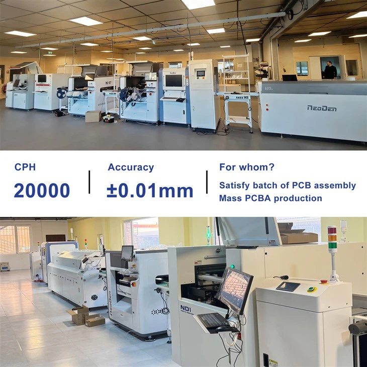
What Does a Pick and Place Machine Do?
If we break down the entire PCB assembly process, the operation of a pick and place machine can be summarized as a series of consecutive actions:
Feeding → Picking → Identification → Positioning → Placement
First, the feeder delivers electronic components to the designated pickup position; then, the placement head uses a nozzle to pick up the component. After the vision system identifies the PCB reference points and components, the machine calculates the actual position and angle based on the program and finally places the component accurately onto the corresponding pad on the PCB.
Therefore, a pick and place machine does more than simply "automatically place components." It actually consists of a feeding system, nozzle, placement head, vision system, motion control system, and software working together to complete an automated placement process.
How does a pick and place machine work?
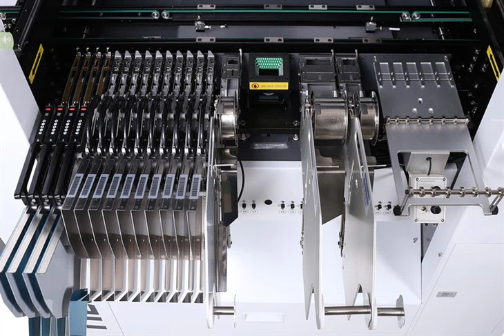
Step 1: The feeder delivers electronic components to the pick-up position
SMT components are packaged in various forms, with common types including tape, stick, and trays, therefore, SMT placement machines require different feeding methods.
The NeoDen N10P SMT machine supports tape feeders, stick feeders, and tray feeders. The tape feeder is used for tape-and-reel components, the stick feeder for stick-packaged components, and the tray feeder is primarily used for devices such as ICs.
Although a feeder may appear to be merely a feeding component, it significantly impacts production stability. If the feeding position is misaligned, or if the tape reel or feeder is installed incorrectly, feeding abnormalities or subsequent pickup failures may occur.
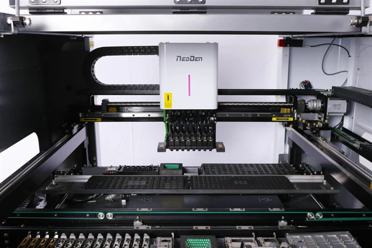
Step 2: Nozzle Picks Up Electronic Components
Once a component reaches the pickup position, the nozzle on the placement head sucks it up.
The nozzle can be thought of as the "tool" that makes direct contact between the SMT placement machine and the electronic component. Since components vary in size, shape, and weight, a single type of nozzle cannot be used for all applications.
In the NeoDen N10P SMT machine, the software can configure the appropriate nozzle based on component information while adjusting parameters such as the pick-up position and pick-up height. For different types of chips, the pick delay must also be adjusted according to actual pick-up conditions.
If issues such as pickup failure, component overturning, or component ejection occur, the nozzle status, pickup position, and pickup height should be the first items to check.

Step 3: The Vision System Identifies the PCB and Components
After a component is picked up, the machine still needs to determine two things:
1. Where is the PCB? What is the status of the component?
This is where the vision system comes into play.
The NeoDen N10P is equipped with a Dual Mark Camera, a Front Flying Camera, and an IC Camera.
Among these, the Mark Camera is primarily used to identify fiducial marks on the PCB. Since the PCB may experience slight positional and angular deviations during the actual loading process, the machine needs to reconfirm the PCB's actual position using these reference points.
The NeoDen N10P's Fiducial Align function calculates the current origin and angle based on the PCB's fiducial marks, then corrects the placement position accordingly.
Meanwhile, the Flying Camera and IC Camera are responsible for component recognition. The N10P software provides functions such as Fly Calib, IC Calib, and IC Rotate Calib, which enable different types of visual recognition and angle correction for standard chips, SOPs, and precision ICs.
Therefore, the vision system does not simply "take a photo" of the components, rather, it plays a role in PCB positioning, component recognition, and placement correction.
2. Why can a pick and place machine place components accurately on the pads?
After vision recognition is complete, the placement head must move to the specified position according to the program and complete the placement.
This step involves multiple parameters, including X/Y motion, pick-up height, place height, component angle, and placement speed.
The NeoDen N10P has a positioning accuracy of ±0.01 mm and uses a magnetic linear encoder for XY motion feedback.
However, in actual SMT production, "equipment accuracy" is not the only factor affecting placement results.
For example, if fiducials are not correctly recognized, the nozzle center is misaligned, or the pick-up position is set incorrectly, component misalignment may still occur even if the equipment itself has high mechanical precision.
Therefore, when encountering placement offset, it is typically necessary to troubleshoot multiple aspects-such as fiducials, PCB origin, nozzle center, pick-up position, and place position-rather than simply assuming that "the machine lacks sufficient precision."
For components smaller than 0402 and precision ICs, the placement speed must also be set appropriately. The NeoDen N10P software allows adjustment of the X/Y Move Speed and Place Speed; for precision components, the movement speed can be appropriately reduced to balance efficiency with placement stability.
What are the main components of a placement machine?
To understand a placement machine, start by familiarizing yourself with the following core components:
| Component | Main Function |
| Feeder | Delivers electronic components to the pick position |
| Nozzle | Picks up components from the feeder |
| Placement Head | Picks up components from the feeder |
| Fiducial Camera | Identifies PCB reference points |
| Flying Camera | Identifies common SMT components |
| IC Camera | Identifies ICs and other devices |
| XY Motion System | Controls the movement of the placement head |
| Software | Handles programming, parameter settings, and production control |
| PCB Track | Conveys and positions the PCB |
These components do not operate independently. For example, the Feeder determines whether components can be fed stably to the pick-up position; the Nozzle determines whether components can be picked up stably; the Camera is responsible for identification and positioning; and the motion system is responsible for completing placement according to the program.
This is also what distinguishes SMT automation equipment from simple mechanical equipment.
What are the core functions of a pick and place machine?
From a practical production perspective, the functions of a placement machine can be categorized into five types.
First, automatic feeding.
Continuously supplying components via various methods such as tape, stick, and tray.
Second, automatic pickup.
Picking up components from designated positions using the nozzle.
Third, vision recognition.
Positioning the PCB using a fiducial camera and identifying different components using a flying camera and an IC camera.
Fourth, precise placement.
Placing components at target positions based on PCB coordinates, vision recognition results, and program parameters.
Fifth, program control.
The entire placement process is organized through coordinate files, the component library, feeder settings, and the Auto Program feature.
The NeoDen N10P's Auto Program feature generates a placement plan based on nozzle usage after component information is entered, displaying the nozzle distribution, feeder distribution, and placement sequence. Automatic programming is completed once the user confirms the plan.
What is the difference between an SMT placement machine and manual placement?
Manual placement still has its place for small quantities of components or simple repairs. However, as the number of components on a PCB increases-especially when it includes a large number of small SMT components-manual operations are limited by efficiency, repeatability, and operational precision.
In contrast, an SMT placement machine can repeatedly perform the same actions according to a pre-set program.
Therefore, for PCB prototypes, R&D, small-batch production, and small-to-medium-sized EMS production, the value of automated placement equipment lies not only in "faster speed" but also in reducing repetitive manual operations and maintaining a more consistent placement process.
What kind of pick and place machine is the NeoDen N10P?
NeoDen N10P is a high-speed pick and place machine designed for SMT automation.
It features 8 placement heads, a maximum placement speed of 20,000 CPH, positioning accuracy of ±0.01 mm, support for 80 tape feeders, and is equipped with 39 nozzle positions and automatic nozzle change.
In terms of vision, the NeoDen N10P is equipped with a dual-mark camera, a flying camera, and an IC camera; for motion control, it uses a magnetic linear encoder; and the software supports coordinate file import and auto-programming.
These features collectively form a comprehensive SMT component placement system, rather than focusing solely on any single parameter.
FAQ
Q1. What is a pick and place machine?
A pick and place machine is a type of SMT automation equipment used to pick up electronic components from feeders and place them accurately at designated locations on a PCB.
Q2. What does a placement machine do?
It is primarily responsible for the automatic placement of electronic components during the PCB assembly process and is one of the core pieces of equipment in an SMT production line.
Q3. How does a placement machine work?
The basic process is feeding → picking → vision recognition → position correction → placement.
Q4. What is an SMT feeder?
A feeder is the feeding device of a placement machine, responsible for conveying electronic components from reels, tubes, or trays to the designated pickup position.
Q5. Why does a placement machine need a vision system?
The vision system is used to identify PCB reference points and electronic components, and helps the machine determine their actual position and orientation.
Q6. How fast is the NeoDen N10P?
The NeoDen N10P has a maximum placement speed of 20,000 CPH.
Q7. How many feeders can the NeoDen N10P accommodate?
The N10P supports up to 80 tape feeders and is compatible with both stick and tray feeders.

Conclusion
If you had to explain what a pick and place machine is in just one sentence, you could say: A pick and place machine is an SMT automation device that automatically and accurately places electronic components onto designated positions on a PCB through feeding, picking, vision recognition, motion control, and software programming.
To truly understand an SMT placement machine, you don't need to memorize all the technical specifications right away. Simply figuring out why feeders supply components, how nozzles pick them up, how vision systems locate them, how the placement head moves, and how software controls the entire process will give you a basic understanding of the machine.
The NeoDen N10P integrates these core functions into a single system, providing an automated placement solution for PCB prototyping, R&D validation, and small- to medium-volume SMT production.
If you are evaluating SMT machines, you can review the detailed specifications of the NeoDen N10P or contact NeoDen for specific equipment recommendations based on your PCB dimensions, BOM, and production volume requirements.